Español
 عربى
عربى русский
Modern communication networks depend on dependable physical connectivity. Although switches, routers, wireless access points, and software receive much of the attention in a network project, the passive cabling system remains the foundation that carries every signal. A poorly designed or difficult-to-install connector can reduce productivity, create maintenance problems, and compromise the performance of an otherwise well-engineered installation. For this reason, the selection of a suitable keystone jack is an important decision for structured cabling contractors, system integrators, distributors, and network owners.
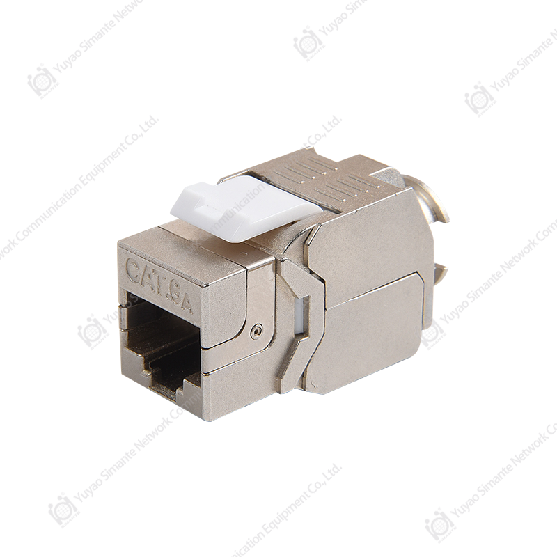
The SMT-1080T8C6A-FTP Shielded Toolless Keystone Jack with Ratchet Lock, Option B, is designed for CAT6A structured cabling applications that require a combination of high-frequency performance, electromagnetic shielding, installation efficiency, and secure cable retention. Its tool-free termination concept helps simplify field work, while the ratchet lock supports a firm and consistent connection between the cable and the jack. The shielded construction is intended for environments in which protection against electromagnetic interference and radio-frequency interference is an important part of the cabling design.
This article examines the product’s construction, working principles, installation advantages, performance value, quality-control considerations, and manufacturing strengths. It also explains why a toolless shielded CAT6A keystone jack can offer practical advantages over conventional connectors that require separate punch-down tools or provide less effective protection against interference.
1. The Role of a CAT6A Keystone Jack in Structured Cabling
A keystone jack is a modular female connector used at the end of a horizontal cable or permanent link. It is commonly installed in wall outlets, patch panels, floor boxes, consolidation points, furniture outlets, and other modular connection systems. Because keystone products use a standardized housing format, one faceplate or panel can often support different types of modules, including copper data jacks, fiber adapters, HDMI modules, telephone connectors, and other low-voltage interfaces.
In a CAT6A network, the keystone jack is part of a channel that may include the permanent horizontal cable, patch panel, patch cords, and active equipment ports. Each component must work together to preserve signal integrity. A connector that is difficult to terminate, inconsistently assembled, or poorly matched to the cable can introduce return loss, insertion loss, crosstalk, or mechanical instability.
CAT6A is widely selected for 10 Gigabit Ethernet applications over suitable balanced twisted-pair cabling. Compared with lower-category systems, CAT6A places greater emphasis on high-frequency performance and alien crosstalk control. The connector must therefore be engineered with attention to contact geometry, pair separation, conductor management, termination consistency, and shielding continuity where a shielded system is required.
The SMT-1080T8C6A-FTP is positioned for this type of application. Its design combines a modular keystone form factor with a shielded body, tool-free termination, and a ratchet-locking mechanism. Together, these features address three practical issues that frequently influence project results: electrical interference, installation time, and cable retention.
2. Product Overview
The product is a shielded toolless CAT6A keystone jack identified as SMT-1080T8C6A-FTP, with Ratchet Lock Option B. The “FTP” designation generally indicates a shielded twisted-pair cabling arrangement in which an overall foil shield is used around the twisted pairs. The jack is therefore intended to participate in a properly designed shielded cabling system, including shielded cable, compatible patch panels, shielded patch cords, and appropriate grounding or bonding practices.
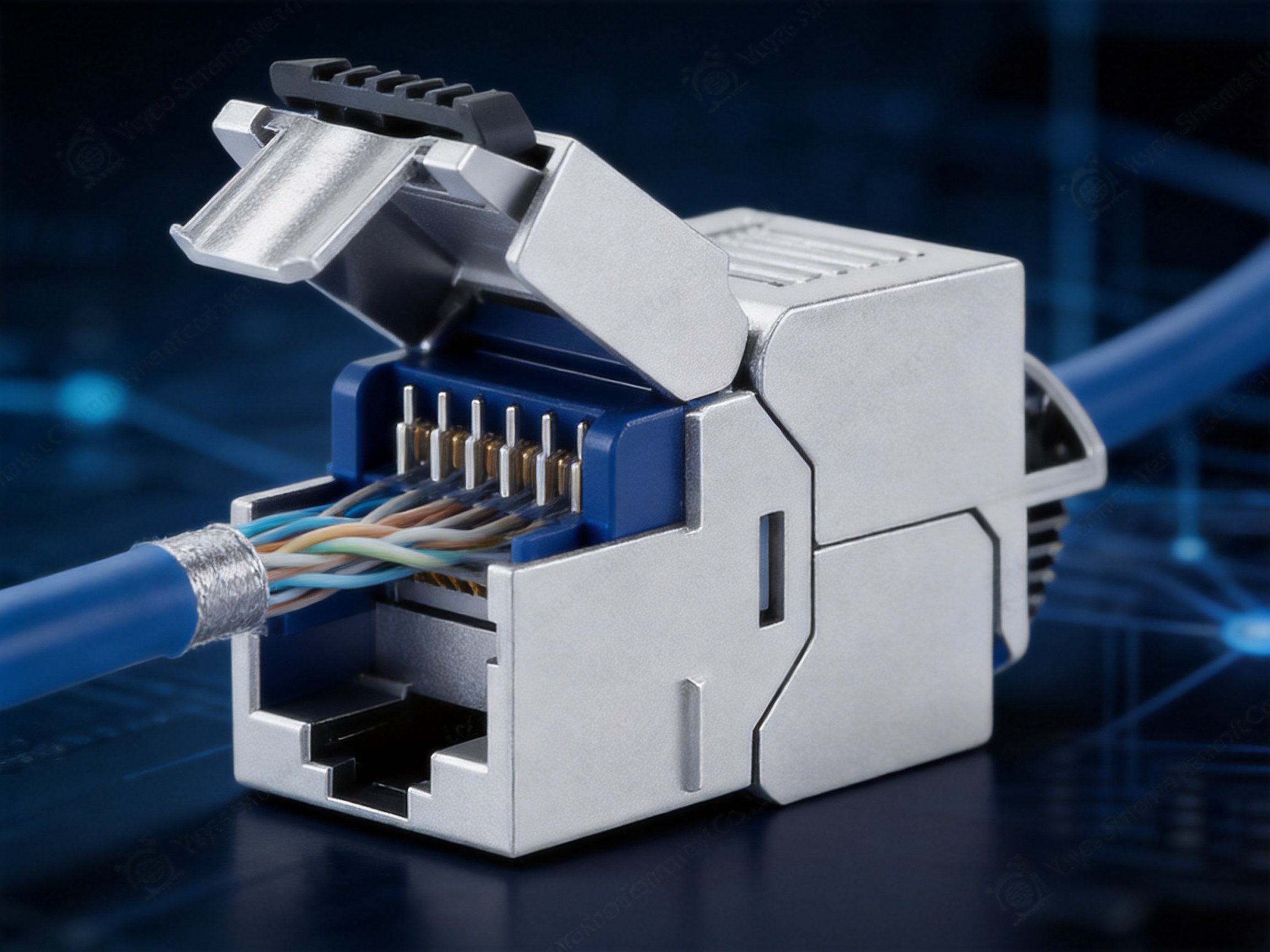
The toolless structure is intended to allow the installer to terminate the cable without relying on a separate impact punch-down tool. The cable conductors are positioned according to the required wiring scheme, and the rear termination assembly is closed or secured so that the contacts engage the conductors. This approach can reduce the number of tools required at the work location and help standardize installation procedures across different teams.
The ratchet lock is a mechanical retention feature. Its purpose is to hold the termination assembly securely after it has been closed. Compared with a simple friction-fit cover, a ratchet mechanism can provide a more controlled locking action and a tactile indication that the assembly has reached its intended position. This can help reduce the possibility of an incompletely closed termination cover or an accidental release during cable management.
The jack is suitable for modular installations where a compact and professional appearance is required. It can be used with compatible keystone faceplates, surface boxes, patch panels, and other modular accessories. Final compatibility should always be verified against the dimensions and specifications of the selected supporting hardware.
| Product Feature | Practical Function | Project Value |
|---|---|---|
| CAT6A-oriented design | Supports high-frequency structured cabling requirements when correctly installed | Suitable for demanding data and 10 Gigabit Ethernet infrastructure |
| Shielded construction | Helps maintain a screened connection path in compatible shielded systems | Useful in areas with electromagnetic or radio-frequency interference concerns |
| Toolless termination | Allows cable termination without a separate punch-down tool | Reduces installation complexity and supports faster field work |
| Ratchet lock | Secures the termination assembly in a defined closed position | Improves mechanical retention and installation confidence |
| Keystone modular format | Fits compatible modular panels and faceplates | Supports flexible deployment and consistent outlet design |
| Manufacturing customization capability | Allows product and packaging adaptations for project needs | Supports OEM, ODM, and distributor programs |
3. Why Shielding Matters in CAT6A Networks
Electrical equipment can generate electromagnetic energy that affects nearby communication cables. Motors, variable-frequency drives, fluorescent lighting systems, power distribution equipment, industrial machinery, elevators, and densely packed server-room infrastructure may create conditions in which interference becomes a design concern. Even where interference is not severe enough to cause an obvious outage, it can reduce the margin available for reliable high-speed transmission.
A shielded cabling system uses conductive elements to help reduce the coupling of external electromagnetic energy into the balanced pairs and to limit the radiation of energy from the cable. The connector is an important part of this system because a break in the shield path can reduce the overall benefit of the cable design.
The shielded body of the SMT-1080T8C6A-FTP is intended to support continuity through the connector when used with appropriate shielded cable and compatible shielded infrastructure. The value of the shield is not limited to the jack alone. Performance depends on the complete channel, including correct cable preparation, shield contact, patch-panel design, equipment bonding, and installation practices.
In office environments, shielding may be selected for future-proofing, equipment density, or project standards. In industrial, medical, transportation, broadcast, security, and automation applications, it may be chosen because the surrounding electrical environment is more challenging. A shielded jack gives system designers an additional layer of protection when the cabling architecture calls for a screened solution.
It is important to note that shielding must be installed correctly. A shielded connector connected to an unshielded or improperly bonded system does not automatically create a complete interference-control solution. The product is most effective when integrated into a fully compatible shielded channel designed according to applicable cabling practices and project requirements.
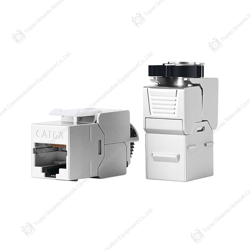
SMT-1080T8C6A-FTP Shielded Toolless Keystone Jack with Ratchet Lock(Option B)
4. Toolless Termination and Field Productivity
Traditional keystone jacks often require an impact punch-down tool. An experienced installer can use such a tool effectively, but the process requires the correct tool, suitable working space, and consistent force. In large projects, the installer may need to carry several tools and accessories between floors, rooms, cabinets, and work areas. Tool availability can become an operational issue, particularly during rapid installation or service work.
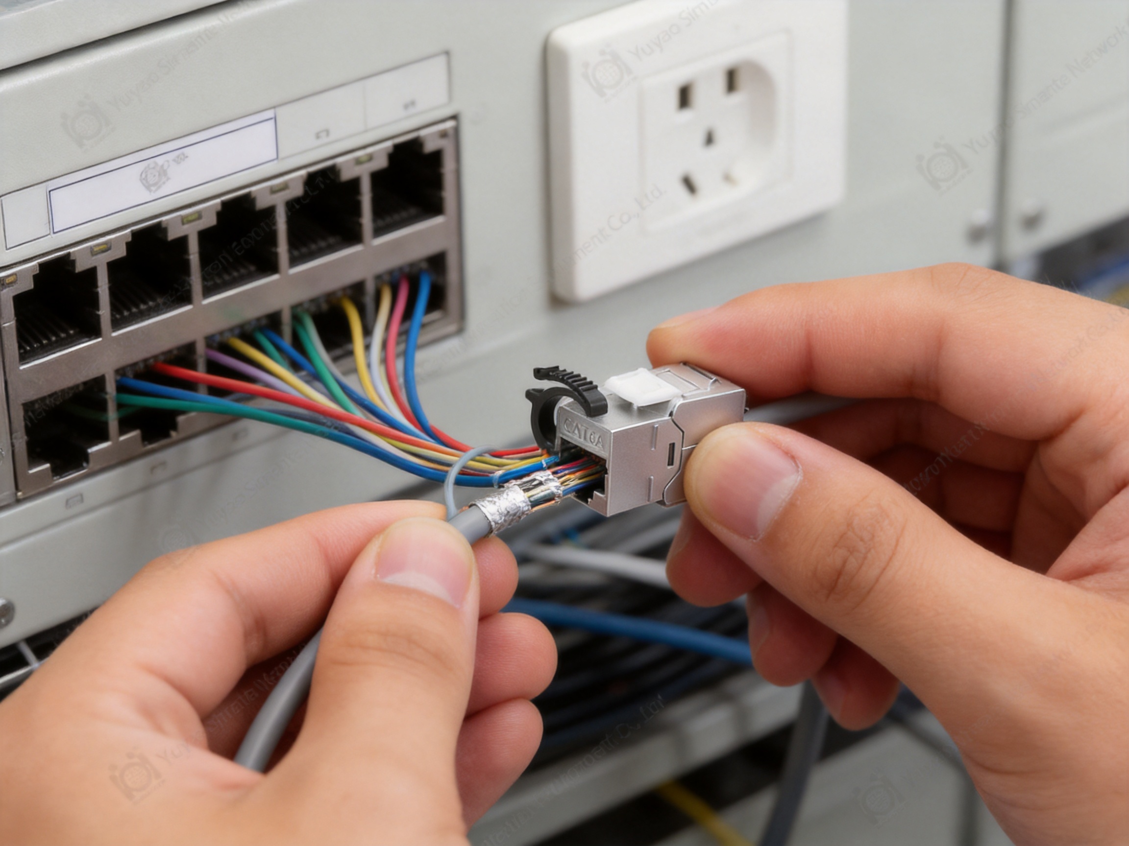
A toolless jack is designed to reduce these practical barriers. The installer generally needs to remove the cable jacket to the specified length, preserve the twist of each pair as much as possible, position the conductors according to the selected wiring pattern, and close the termination assembly. The product’s internal design then performs the contact engagement as the assembly is secured.
This process can provide several advantages. First, it can reduce the time required for each outlet. Second, it can make installation more convenient in confined spaces where using a punch-down tool is difficult. Third, it can reduce dependence on individual striking technique. Fourth, it can support more consistent work procedures for teams with different levels of field experience.
Toolless termination is especially useful in retrofit work, office renovations, data-center expansions, and service calls. A technician can carry a compact set of connectors and basic cable-preparation tools rather than a larger collection of termination equipment. This may reduce setup time and make small repair tasks more efficient.
However, toolless does not mean preparation-free. The cable must still be prepared carefully. Excessive untwisting, damage to the conductors, an incorrect wiring sequence, or inadequate strain relief can affect performance. The installer should follow the product’s termination instructions and use the correct wiring scheme consistently throughout the link.
4.1 Consistency in Termination
One of the strongest arguments for a toolless design is process consistency. With a conventional punch-down jack, the quality of the connection can be influenced by the impact force, tool condition, conductor positioning, and the installer’s technique. A toolless mechanism can help define the closing action and reduce variation between individual terminations.
The ratchet lock adds to this controlled process. As the installer closes the assembly, the ratchet provides a sequence of mechanical engagement points. When properly designed, the locking action helps maintain pressure on the termination components and reduces the possibility that the cover will move after installation.
More consistent mechanical assembly can support more consistent electrical results. It can also help reduce the number of reterminations caused by loose covers, incomplete closure, or accidental movement during cable dressing. This is valuable on projects where hundreds or thousands of outlets must be installed and documented.
4.2 Reduced Tool Dependence
Reducing tool dependence can improve work flow without eliminating the need for training. A contractor can standardize installation around cable cutters, jacket strippers, labeling equipment, and basic inspection tools. This may be particularly beneficial for mobile service teams and installers working in multiple locations.
Toolless termination can also reduce the risk of using a punch-down tool with excessive force. Excessive force may damage a conductor, deform a contact, or crack a plastic component. A controlled closure mechanism is intended to transfer the required force through the jack’s own assembly rather than relying entirely on the installer’s hand pressure and tool technique.
5. The Ratchet Lock Advantage
The ratchet-lock feature is a central element of the product design. A termination mechanism must do more than make initial contact. It must maintain contact during cable movement, installation, maintenance, and long-term service. The ratchet lock supports this objective by mechanically retaining the closure position.
During installation, a tactile ratcheting action can provide useful feedback. The installer can feel the assembly progressing through its locking positions and can identify when the cover or termination component has reached the intended final position. This can be more dependable than a cover that simply snaps into place without a clearly defined locking sequence.
After installation, the lock helps protect the termination from accidental opening. Cable bundles are often moved while patch panels are populated, cabinets are reorganized, or furniture is repositioned. A secure rear assembly helps keep the conductors in their intended contact position.
The ratchet design may also support serviceability. Depending on the specific construction and installation instructions, the assembly may be capable of controlled release or rework. Any retermination should be performed according to the manufacturer’s instructions because repeated handling can affect conductor condition and contact reliability.
Compared with a basic toolless connector without a positive locking system, the ratchet-lock version offers a stronger emphasis on mechanical control. Compared with a conventional punch-down connector, it can simplify installation while still providing a defined retention mechanism. This combination is particularly attractive to installers seeking speed without sacrificing a secure finished connection.
6. Electrical Performance Considerations
A CAT6A connector must be evaluated as part of a high-frequency transmission system. The electrical design must account for insertion loss, return loss, near-end crosstalk, far-end crosstalk, and other parameters relevant to balanced twisted-pair communication. The performance of the completed link is influenced by the connector’s contact geometry, pair layout, dielectric materials, termination accuracy, and compatibility with the cable.
The product’s CAT6A-oriented design is intended for structured cabling systems where high data rates and reliable signal transmission are required. The connector should preserve pair balance and keep the conductors arranged in a controlled manner. Excessive separation of the twisted pairs during termination can increase crosstalk and reduce performance margin.
For this reason, cable preparation is important. The installer should remove only the required amount of jacket, maintain the pair twists as close to the termination point as the design permits, and avoid unnecessary bending or deformation. The cable should also be supported so that tension is not transferred directly to the contact area.
Testing remains essential. A completed installation should be verified using suitable field-test equipment and the test limits specified for the project. Visual inspection, continuity checks, wire-map testing, and category-appropriate certification can identify problems that may not be visible from the outside of the jack.
The product should not be treated as a substitute for complete channel design. The cable category, patch cords, patch panels, plugs, grounding approach, and installation method must be compatible. When all components are selected and installed appropriately, the jack can contribute to a stable and organized CAT6A link.
6.1 Pair Management
Pair management is one of the key design factors in high-performance copper connectors. The four pairs in a balanced data cable must remain correctly identified and positioned. The jack’s rear assembly should guide the conductors toward their correct contacts while minimizing the amount of untwist and crossing.
Clear color coding and a logical termination layout can reduce installation errors. The installer should select either the T568A or T568B wiring pattern according to the project standard and use the same pattern consistently unless a specific application requires otherwise. Inconsistent wiring can create a wire-map fault and prevent proper network operation.
6.2 Shield Continuity
In a shielded installation, the cable shield must make reliable contact with the connector’s conductive structure. The cable’s foil or drain-wire arrangement should be prepared according to the termination instructions. The shield path should then continue through compatible metallic panels, patch cords, and equipment connections as required by the system design.
A shielded jack can provide useful protection only when the shield is properly terminated. Incorrect preparation, damaged foil, an unconnected drain wire, or incompatible unshielded accessories may interrupt the screening system. Installers should verify both electrical performance and the continuity of the intended bonding path.
7. Mechanical Design and Installation Reliability
Mechanical reliability is essential in a connector that may remain in service for many years. The housing must protect the internal contacts, maintain the position of the termination assembly, and withstand normal handling during installation and maintenance. The modular front interface must also remain stable when patch cords are inserted and removed.
The SMT-1080T8C6A-FTP is designed around a compact keystone format, making it suitable for dense modular applications. A well-controlled housing can help keep the contact assembly aligned and can provide a consistent front interface across multiple outlets. This is beneficial for patch panels and faceplates where a uniform appearance and predictable module fit are important.
The ratchet lock supports rear mechanical retention, while the front modular interface supports connection to a patch cord. Both areas must work together. A connector that is electrically sound but mechanically loose can create intermittent faults, especially where cables are moved frequently.
Strain relief is another important consideration. The horizontal cable should be supported near the jack so that its weight and bending force are not concentrated at the termination. Cable managers, tie mounts, and appropriate bend-radius control should be used as part of the overall installation. The jack’s locking structure is most effective when the cable is routed and supported correctly.
A professional installation should also include labeling. Clear identification of the outlet, rack, patch-panel port, and destination makes future service work faster and reduces the chance of accidental disconnection. The modular design of the jack supports organized outlet construction when combined with a disciplined labeling system.
8. Advantages Over Conventional Competitor Designs
Different connector designs may be suitable for different projects, but the shielded toolless ratchet-lock format offers a useful combination of features that is not always available in basic alternatives. The product’s competitive value can be understood by comparing it with common connector categories.
8.1 Compared with Unshielded CAT6A Jacks
An unshielded jack may be sufficient in a conventional office with a controlled electromagnetic environment and an unshielded cabling architecture. However, it does not provide the same screening capability as a shielded connector. In industrial spaces, equipment rooms, high-density technical areas, and facilities with strict project specifications, the lack of a shield may reduce design flexibility.
The shielded construction of this product allows it to be considered for systems in which electromagnetic protection and shield continuity are part of the design objectives. It also gives distributors and installers a broader product option for projects that specify screened components.
8.2 Compared with Tool-Dependent Punch-Down Jacks
Punch-down jacks remain familiar and can perform well when installed with suitable tools and trained personnel. Their disadvantages may include longer preparation time, dependence on tool quality, and greater variation in the force applied by different installers.
The toolless design reduces these limitations. It can simplify field logistics, improve access in restricted spaces, and shorten the termination process. The ratchet lock further helps define the final mechanical condition of the connection.
8.3 Compared with Basic Toolless Jacks
Some toolless products use a simple cover or friction-fit closure. These designs may be quick to install, but the installer may receive less tactile confirmation that the assembly is fully secured. A ratchet-lock mechanism provides a more deliberate closure sequence and can improve confidence during installation.
The difference becomes more important in large projects, where a small percentage of incomplete closures can lead to repeated troubleshooting. A positive locking system can support quality assurance by making the installation action more visible and repeatable.
8.4 Compared with Poorly Integrated Shielded Designs
Shielding must be integrated into the connector rather than treated as a decorative metal component. The conductive body, cable shield contact, termination assembly, and supporting hardware must work together. A product with a carefully integrated shielded structure can offer more practical value than a connector that merely adds a metal cover without a reliable continuity path.
The product’s focused design as a shielded CAT6A jack allows buyers to evaluate it as part of a complete screened cabling solution. Detailed project validation should still be carried out, but the design direction is aligned with applications that need more than a basic unshielded module.
9. Manufacturing Strengths and Production Capability
The quality of a network connector begins long before the product reaches the installation site. It depends on material selection, mold precision, contact forming, assembly control, inspection discipline, and the ability to maintain stable production over time. Yuyao Simante Network Communication Equipment Co., Ltd. combines product design, development, sales, and service in one manufacturing organization.
The company has nearly 20 years of service experience in network cabling solutions and optical fiber products. This period of market involvement provides an important foundation for understanding the practical requirements of installers, distributors, structured cabling contractors, and OEM customers.
A mature research and development system supports product quality from the design stage. Design decisions influence the final performance of a keystone jack in many ways, including the internal geometry, housing tolerances, contact positioning, locking force, shield structure, and compatibility with cable sizes. When engineering and production teams work closely together, design changes can be evaluated more efficiently and manufacturing problems can be addressed at their source.
The company reports more than 10 engineers and over 30 full-time technical personnel. This technical structure supports ongoing product improvement, process supervision, quality analysis, and customer service. A dedicated technical team is particularly valuable for products that require precise assembly and consistent mechanical action, such as toolless connectors with integrated locking systems.
9.1 Injection Molding Capability
The company operates fully automatic and semi-automatic injection molding equipment. Injection molding is critical for producing the polymer housings, covers, wire-management components, and other molded parts used in modular connectors. Mold quality and process stability directly affect dimensions, surface finish, snap-fit behavior, and the alignment of internal components.
Automatic injection molding can support repeatable cycle control and stable output. Semi-automatic equipment can provide flexibility for different product structures, order volumes, or customized components. The combination allows the manufacturer to balance efficiency with product variety.
For a ratchet-lock keystone jack, molding precision is especially important. The locking teeth, hinge areas, cable guides, and internal support features must be formed accurately. Variations in these areas may change the closing force or affect the final position of the termination assembly. Controlled molding helps the assembled product achieve predictable mechanical behavior.
9.2 Automatic Assembly and Installation Equipment
The factory has multiple automatic installation machines and maintains 10 regular and customization production lines. Automated or semi-automated assembly can improve consistency in operations such as contact placement, component insertion, cover installation, and mechanical testing.
Automation does not eliminate the need for quality personnel. Instead, it provides a repeatable production platform that can be combined with inspection, sampling, and process controls. In high-volume connector manufacturing, automation can reduce handling variation and help maintain stable output across production batches.
The reported annual output of more than 9 million units demonstrates the company’s ability to support substantial demand. Capacity is important for distributors and large project contractors because supply continuity can be just as important as the specification of an individual product. Stable production can help reduce delays caused by shortages or inconsistent batch availability.
9.3 Custom Production, OEM, and ODM Support
Structured cabling customers may require more than a standard catalog product. They may need private labeling, customized packaging, modified color options, documentation adaptations, project-specific accessories, or changes to the product configuration. The company’s customization production lines support this type of business requirement.
OEM and ODM capability can benefit distributors that want to build a distinct product range. It can also help system suppliers align connector appearance and packaging with their own market identity. For large projects, customization may simplify procurement by allowing a product and its documentation to be prepared around the customer’s installation procedure.
Customization should be managed carefully. Any change to the connector’s materials, contact structure, shield arrangement, or termination mechanism should be evaluated for mechanical and electrical impact. A capable manufacturer should be able to coordinate design review, sample approval, process validation, and production inspection before a customized item is released.
10. Quality Management and Product Testing
Network connectors are small components, but they require precise quality control. A minor defect in a contact, latch, housing, or termination cover can affect installation efficiency or long-term reliability. Quality management should therefore cover incoming materials, molded components, metal parts, assembly operations, finished goods, and packaging.
The company emphasizes strict production management and performance testing. This approach is important because a connector’s quality cannot be judged by appearance alone. A polished housing may still contain a contact-positioning problem, while a visually acceptable termination assembly may not maintain the required electrical characteristics.
10.1 Material and Component Inspection
Materials used in the jack should be checked for conformity with the intended design. Molded parts should be inspected for dimensional stability, deformation, flash, cracking, and surface defects. Metal shield components should be checked for correct shape, fit, and surface condition. Contacts should be evaluated for position, finish, and resistance to mechanical displacement.
Material control is especially important when products are manufactured in high volume. Consistent polymer behavior supports stable molding, while consistent metal properties support reliable contact action and shield assembly. Supplier qualification and incoming inspection help reduce variation before components enter production.
10.2 Assembly Inspection
Assembly inspection can confirm that each contact, cover, shield, and locking feature is correctly installed. Operators or automated systems may check the position of internal parts, the operation of the ratchet, and the engagement of the front modular interface.
Functional checks are valuable because they evaluate the product as a working assembly rather than as a collection of separate components. A ratchet lock should close with an appropriate action and remain secure. The termination components should remain aligned. The shield should fit as designed and should not interfere with the connector’s installation into a compatible panel or faceplate.
10.3 Performance Testing
Performance testing may include electrical continuity, contact resistance, insulation behavior, wire-map verification, and category-related high-frequency measurements. The precise test program should be based on the product specification, applicable standards, customer requirements, and the intended market.
For CAT6A products, production validation should pay close attention to crosstalk and return-loss behavior. These characteristics can be influenced by small changes in contact position, pair separation, plastic geometry, and termination pressure. A structured testing program helps identify process drift and supports continuous improvement.
Shielded products may also require checks of shield continuity and contact between the cable shield interface and the connector’s conductive body. These tests can help confirm that the screening path is present when the product is terminated correctly.
10.4 Reliability and Handling Tests
Mechanical tests may evaluate plug insertion and withdrawal, latch operation, cover retention, cable retention, and repeated handling. Such tests are relevant because connectors are often installed in areas where patch cords are changed regularly or where cabinet access requires repeated movement of cable bundles.
Environmental evaluation may be appropriate depending on the target application. Temperature, humidity, corrosion exposure, vibration, and material flammability requirements can vary by region and project type. Buyers should request the applicable technical documentation when a product is intended for a specialized environment.
11. Installation Procedure and Best Practices
A successful installation begins with selecting the correct cable, wiring pattern, panel, and accessories. The installer should confirm that the cable diameter and conductor construction are compatible with the jack. Shielded cable should be matched with compatible shielded connectors and supporting hardware.
11.1 Prepare the Work Area
Before termination, organize the cable route and ensure that sufficient slack is available for future service. Excessive tension should not be applied to the cable. The work area should be clean and adequately lit so that the conductors, color codes, and shield components can be identified clearly.
11.2 Prepare the Cable
Remove the outer jacket carefully without nicking the insulated conductors or damaging the foil shield. Use the length recommended in the installation instructions. Avoid exposing more conductor length than necessary, and retain the twists of each pair as close to the termination point as practical.
Prepare the shield and drain wire according to the jack’s design. The shield must be positioned so that it contacts the intended conductive area. Do not cut away shield components that are required for continuity, and do not leave loose metallic material that could interfere with the modular housing.
11.3 Arrange the Conductors
Select the T568A or T568B wiring pattern required by the project. Place each conductor into the corresponding channel or guide. Confirm the colors before closing the termination assembly. Conductors should be fully seated and should not be crossed unnecessarily.
11.4 Close the Ratchet Assembly
Close the termination cover or locking component in the direction specified by the product instructions. Apply steady pressure and observe the ratcheting action. Confirm that the assembly has reached its final locked position and that no conductor has shifted out of its guide.
11.5 Install and Test the Jack
Insert the completed jack into the compatible faceplate, patch panel, surface box, or other modular support. Verify that the retaining tabs engage correctly and that the module sits flush. Label the port and connect the cable to the appropriate destination.
Perform a wire-map test before finalizing the outlet. For projects requiring certified CAT6A performance, use an approved field tester and retain the test results as part of the installation documentation.
12. Applications
The shielded toolless CAT6A keystone jack can be considered for a wide range of structured cabling applications. In commercial offices, it can support organized data outlets and modular workstation connectivity. In server rooms and equipment rooms, it can be used in patch panels and cross-connect areas where cable density and serviceability are important.
Industrial facilities may benefit from the shielded construction when communication cables are routed near machinery, power equipment, or motor controls. Automation systems, production lines, building-management systems, and security infrastructure may also require organized copper connectivity with additional interference-control considerations.
Educational institutions, hospitals, hotels, transportation facilities, and public buildings often require large numbers of consistent outlets. The toolless installation method can support faster deployment, while the modular keystone format helps maintain a uniform appearance across different rooms and departments.
Smart-home and building-automation installations can also use modular data outlets. Although many modern devices communicate wirelessly, fixed copper links remain valuable for access points, cameras, control systems, gateways, and equipment requiring dependable bandwidth. A shielded connector gives the system designer another option where local electrical conditions or project standards justify it.
13. Procurement and Project Selection Guidance
When selecting a CAT6A keystone jack, buyers should consider the complete project rather than focusing on one feature. The first question is whether the network requires a shielded or unshielded architecture. If shielding is selected, all major components should be reviewed for compatibility.
The second question concerns installation method. Toolless termination may be especially valuable when installation speed, limited workspace, or reduced tool logistics are priorities. Contractors should also consider the training level of the installation team and whether the ratchet-lock action fits the project’s quality-control procedure.
The third question concerns product integration. The jack should fit the selected faceplate, panel, surface box, or furniture outlet. The front interface should accommodate the planned patch cords without excessive stress. The rear cable-entry area should support the cable diameter and bend radius required by the project.
The fourth question concerns documentation and testing. Buyers should request product drawings, installation instructions, material information, test data, and applicable compliance documentation. Large projects may also require samples, first-article approval, packaging specifications, and batch traceability.
The fifth question concerns supply capability. A manufacturer with multiple production lines, injection molding capacity, automatic assembly resources, and customization experience may be better positioned to support ongoing projects. Consistent supply is especially important when a connector is being deployed across a large building or a multi-site network.
14. Sustainability, Serviceability, and Long-Term Value
Long-term value is not limited to the initial purchase price. A connector that installs quickly, reduces rework, and remains easy to service can lower the total cost of ownership. Toolless termination may reduce labor time, while reliable mechanical retention may reduce troubleshooting related to loose or incomplete connections.
Modular keystone systems also support serviceability. If an outlet needs to be replaced or upgraded, the individual module can often be handled separately from the faceplate or panel. This modular approach may reduce disruption during maintenance and allow a facility to adapt its connectivity over time.
Manufacturing efficiency can contribute to responsible resource use by reducing scrap, rework, and unnecessary replacement. Stable molding and assembly processes help manufacturers use materials more consistently. Quality testing also reduces the risk that defective products will reach a job site, where replacement may require additional transportation and labor.
Packaging design, shipping efficiency, and product consolidation may provide further environmental benefits. Buyers seeking sustainability information should request specific material, packaging, and manufacturing data from the supplier rather than relying only on general product descriptions.
15. Role of the Manufacturer as a Technical Partner
A network-component manufacturer provides more value when it can support the customer before, during, and after production. Product selection, sample evaluation, installation guidance, packaging coordination, and technical communication all influence the success of a cabling project.
Yuyao Simante Network Communication Equipment Co., Ltd. presents itself as a manufacturer of network cabling solutions and optical fiber products, with a product range that includes keystone jacks, patch panels, wall faceplates, data sockets, and related components. This broader product scope can help customers coordinate multiple parts of a structured cabling system through one experienced source.
The company’s engineering and technical personnel support product updates and quality improvement. Its production lines and molding equipment provide a platform for both standard products and customized programs. Its reported export activity in Europe, Australia, Africa, the Middle East, and Southeast Asia also indicates experience in serving different international markets and customer requirements.
For OEM and ODM buyers, the ability to communicate directly with a factory can simplify design review and reduce unnecessary intermediaries. For distributors, factory support can help with product training, technical documentation, and stable replenishment. For contractors, clear installation guidance and responsive technical service can reduce uncertainty during deployment.
16. Frequently Asked Questions
Q1: What type of product is the SMT-1080T8C6A-FTP?
It is a shielded, toolless CAT6A keystone jack with a ratchet-lock termination mechanism. It is intended for modular structured cabling installations using compatible shielded twisted-pair cabling and accessories.
Q2: What does “toolless” mean for this keystone jack?
Toolless means that the cable termination is designed to be completed without a separate impact punch-down tool. The installer still needs to prepare the cable, arrange the conductors correctly, and close the termination assembly according to the product instructions.
Q3: What is the purpose of the ratchet lock?
The ratchet lock secures the termination assembly in a defined closed position. It helps maintain mechanical pressure and provides tactile feedback during installation, reducing the possibility of an incompletely closed termination cover.
Q4: Why choose a shielded jack instead of an unshielded jack?
A shielded jack may be appropriate where electromagnetic interference, radio-frequency interference, equipment density, industrial machinery, or project specifications make screening desirable. It must be used as part of a complete compatible shielded cabling system.
Q5: Can this product be used with any CAT6A cable?
Compatibility depends on the cable’s conductor size, insulation structure, outer diameter, shield type, and the jack’s specified range. Buyers should confirm the technical data and installation instructions before selecting the cable and connector combination.
Q6: Is the connector suitable for 10 Gigabit Ethernet?
The product is designed for CAT6A structured cabling applications, which are commonly associated with 10 Gigabit Ethernet over suitable balanced twisted-pair channels. Actual network performance depends on the complete channel, installation quality, cable type, patch cords, and test results.
Q7: Should T568A or T568B be used?
Either wiring pattern may be required depending on the project standard. The important principle is consistency. The selected pattern should be followed at both ends of the permanent link unless a documented application requires a different arrangement.
Q8: Does a shielded jack automatically ground the network?
No. The jack can support shield continuity, but grounding and bonding depend on the complete cabling system, patch panels, rack hardware, patch cords, active equipment, and facility grounding design. A qualified installer should verify the project’s grounding requirements.
Q9: Can the jack be used in patch panels and wall outlets?
Its keystone format is intended for compatible modular panels, faceplates, surface boxes, and similar accessories. The specific dimensions and retaining features should be checked against the selected panel or outlet before installation.
Q10: What testing should be performed after installation?
At minimum, the installation should be inspected and checked for correct wire mapping and continuity. Where required by the project, a suitable field tester should certify the link against the applicable CAT6A performance limits. Shield continuity should also be verified in a screened installation.
Q11: What manufacturing capabilities support this product?
The manufacturer reports an established research and development system, more than 10 engineers, over 30 full-time technical personnel, automatic and semi-automatic injection molding equipment, automatic installation machines, 10 regular and customization production lines, and annual output exceeding 9 million units across its product range.
Q12: Does the manufacturer support customized products?
Yes. The company undertakes OEM and ODM projects and maintains customization production lines. Customization requirements should be discussed in advance, including product structure, labeling, color, packaging, documentation, testing, and minimum order expectations.
Q13: What installation mistake most often affects performance?
Common problems include excessive untwisting, incorrect conductor order, damaged insulation, incomplete locking, poor cable support, excessive bending, and incorrect shield preparation. Careful preparation and post-installation testing help identify and prevent these issues.
Q14: Is a toolless connector always better than a punch-down connector?
Not necessarily. The best choice depends on the project, installer preferences, cable type, maintenance requirements, and technical specification. A toolless ratchet-lock connector is advantageous where quick, controlled, and convenient termination is valuable.
17. Conclusion
The SMT-1080T8C6A-FTP Shielded Toolless Keystone Jack with Ratchet Lock, Option B, brings together several features that address the practical needs of modern structured cabling. Its CAT6A-oriented design supports high-frequency copper infrastructure, while the shielded construction is intended for systems that require a screened connection path. The toolless termination method can simplify field installation, reduce tool dependence, and improve productivity. The ratchet lock adds mechanical control and helps secure the termination assembly after closure.
Its competitive advantage lies in the combination of these features rather than in any single characteristic. Compared with unshielded products, it offers a solution for shielded cabling architectures. Compared with tool-dependent connectors, it can make termination more convenient. Compared with basic toolless designs, the ratchet mechanism provides a more deliberate locking action and stronger installation feedback.
The manufacturer’s engineering resources, molding equipment, automatic assembly capability, multiple production lines, customization support, and international service experience provide additional value for distributors, contractors, system integrators, and OEM customers. These resources help support product consistency, supply continuity, design updates, and project-specific requirements.
For best results, the jack should be selected as part of a complete CAT6A channel. Correct cable compatibility, shield preparation, wiring-pattern consistency, cable support, modular fitting, and field certification are all necessary. When these practices are followed, a shielded toolless keystone jack with ratchet lock can contribute to a faster, more organized, and more dependable structured cabling installation.
References
1. ISO/IEC 11801, Information Technology—Generic Cabling for Customer Premises.
2. ANSI/TIA-568.2-D, Balanced Twisted-Pair Telecommunications Cabling and Components Standards.
3. ANSI/TIA-606, Administration Standard for Telecommunications Infrastructure.
4. ANSI/TIA-607, Generic Telecommunications Bonding and Grounding for Customer Premises.
5. IEC 61935-1, Testing of Balanced Communication Cabling in Accordance with ISO/IEC 11801.
6. IEC 60512, Connectors for Electronic Equipment—Tests and Measurements.
7. Manufacturer product information for SMT-1080T8C6A-FTP Shielded Toolless Keystone Jack with Ratchet Lock, Option B.
8. Manufacturer information concerning network cabling solutions, optical fiber products, injection molding, automatic assembly, quality control, OEM, and ODM services.
9. General structured cabling installation and testing practices for balanced twisted-pair communication systems.