Español
 عربى
عربى русский
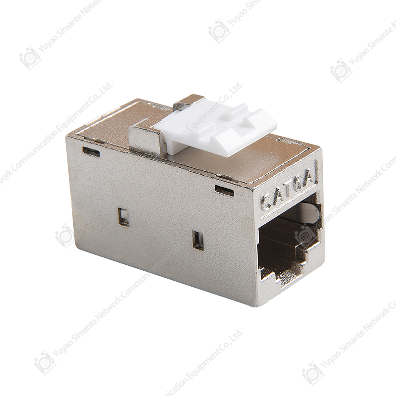
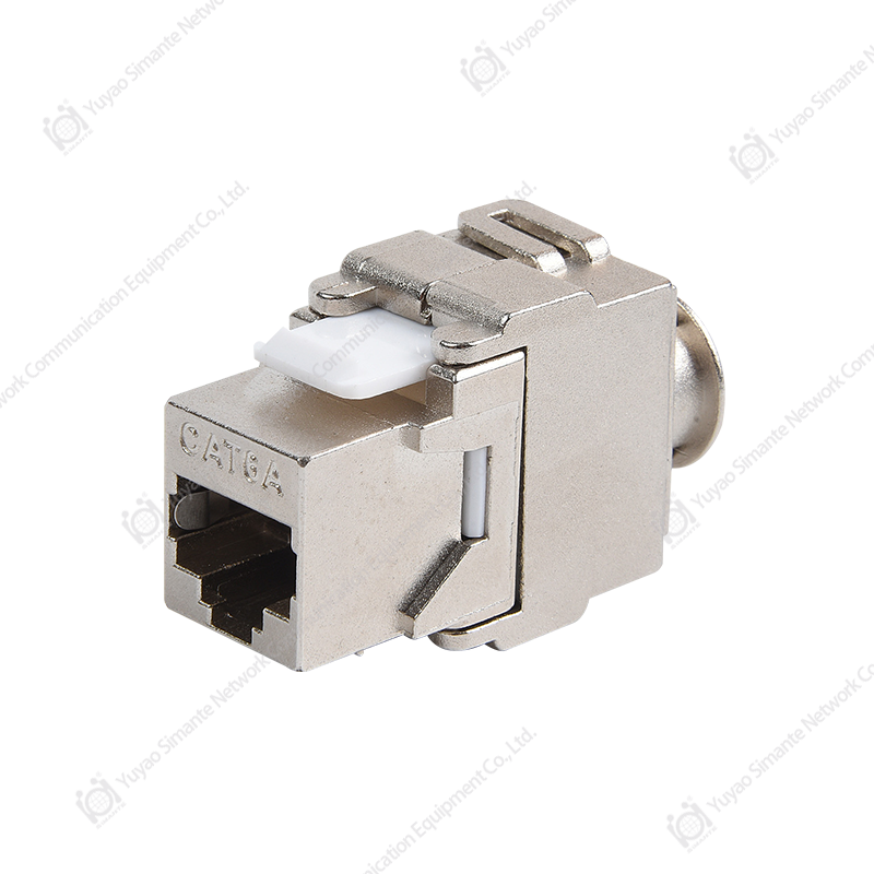
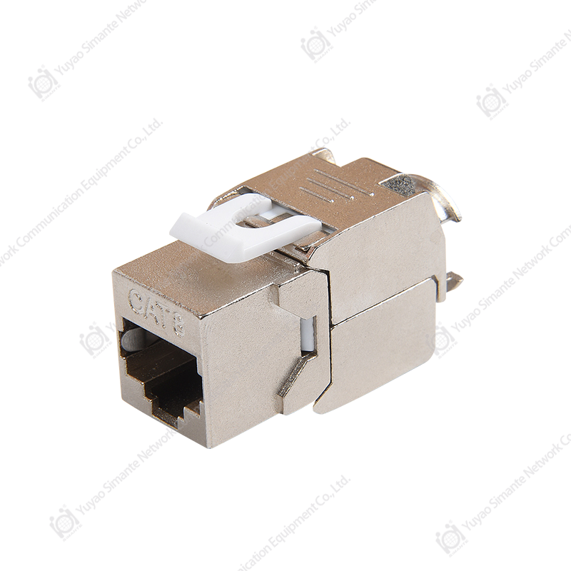
Modern data networks depend on reliable physical infrastructure. Although switches, routers, wireless access points, and cloud services receive much of the attention, the passive cabling system remains the foundation that connects every device. A poorly selected jack, inconsistent termination method, or inadequate electromagnetic interference protection can reduce the performance of an otherwise advanced network. The 180-degree shielded CAT6A toolless keystone jack is designed to address these challenges with a compact form, high-frequency transmission capability, tool-free termination, and all-round shielding.
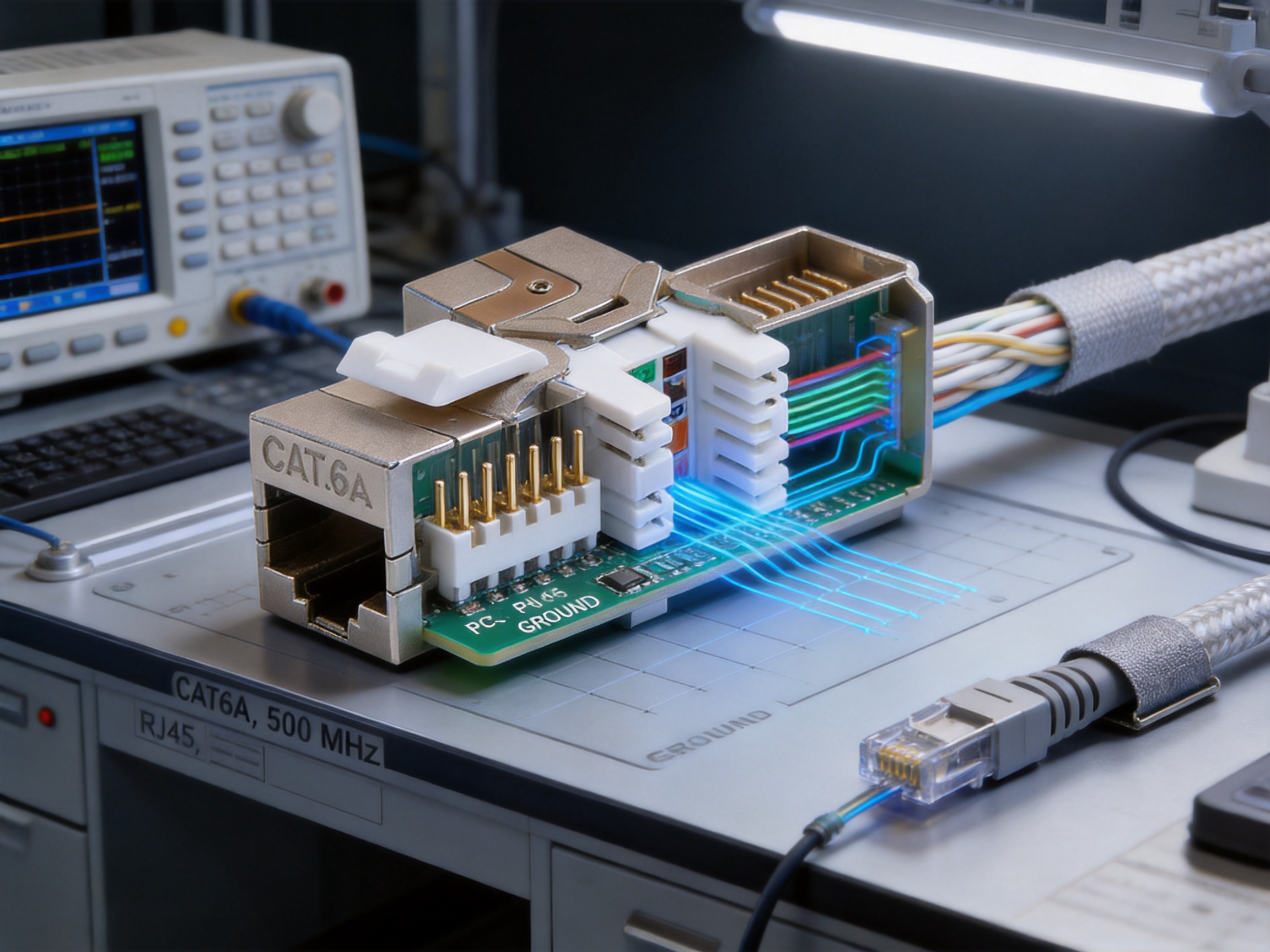
The SMT-1047T8C6A-FTP is a CAT6A keystone jack developed for structured cabling systems, communication outlets, patch panels, distribution frames, and equipment-to-work-area connections. It supports both T568A and T568B wiring sequences and is suitable for horizontal cabling and work-area cabling based on balanced twisted-pair copper conductors. Its embedded modular design allows it to be installed in compatible patch panels and modular distribution frames, while its 180-degree configuration helps installers manage cable routing in confined spaces.
The product combines a zinc alloy die-cast shield, clearly marked wiring instructions, tool-free IDC termination, phosphor bronze contacts, and carefully selected plastic materials. These features provide a practical alternative to conventional unshielded or more complicated jacks, particularly where electromagnetic compatibility, installation efficiency, and long-term serviceability are important.
Product Overview
A keystone jack forms the connection point between horizontal network cabling and the equipment or patch cord used in the work area. It must provide stable electrical contact, withstand repeated insertion and removal, maintain the cable pair geometry, and fit accurately into standardized panels and faceplates. In a CAT6A system, the jack must also support higher transmission frequencies and manage crosstalk more effectively than lower-category components.
The SMT-1047T8C6A-FTP is designed as a universal connector-level 2 module. Its compact embedded construction enables it to be integrated into modular distribution frames, patch panels, wall outlets, and other structured cabling hardware. The front interface uses an RJ45 jack for patch-cord connection, while the rear IDC section is used to terminate horizontal cable.
The 180-degree design provides a practical orientation for cable entry and routing. Instead of forcing the cable to bend sharply around the rear of a standard jack, the installer can guide the cable through a more controlled path. This is especially useful in high-density cabinets, shallow wall boxes, compact faceplates, and patching areas where cable-management space is limited.
The product is suitable for commercial buildings, data rooms, industrial offices, educational facilities, residential network installations, smart-home infrastructure, automation systems, and other applications requiring a shielded CAT6A copper connection. Its compatibility with both T568A and T568B sequences also helps contractors standardize installation procedures across different projects.
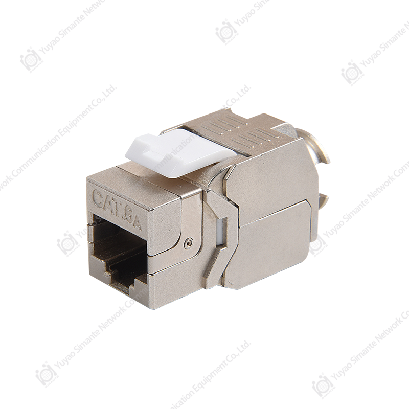
SMT-1047T8C6A-FTP 180 Degree Shielded CAT6A Toolless Keystone Jack
Key Design Advantages
CAT6A Transmission Capability
CAT6A cabling is widely used when a network must support demanding data applications and increased bandwidth over balanced copper links. The jack is specified for a frequency range of 1 to 500 MHz, making it suitable for CAT6A-oriented structured cabling systems when installed with compatible cables, patch panels, connectors, and patch cords.
Network performance depends on the complete channel rather than one component alone. For this reason, the use of a CAT6A jack should be combined with CAT6A horizontal cable, suitable patch cords, correctly rated patch panels, and proper installation practices. When all components are matched appropriately, the jack can contribute to a stable, high-performance copper channel.
The internal contact arrangement uses high-low dislocation technology. This design helps separate contact positions and reduce near-end crosstalk within the connector area. Crosstalk is an important consideration in high-frequency systems because signals traveling through adjacent pairs can interfere with one another. By carefully arranging the contacts and controlling the internal geometry, the design supports improved signal integrity compared with a basic connector layout.
360-Degree Shielding
One of the product’s most important distinguishing characteristics is its 360-degree all-round shielding shell. The shell is made from zinc alloy through die-casting, creating a continuous metal enclosure around the connection area. This structure is designed to limit the influence of external electromagnetic interference and reduce the possibility of unwanted radiation from the cable system.
Shielding can be especially valuable in environments containing motors, variable-frequency drives, fluorescent lighting systems, power distribution equipment, industrial controls, medical equipment, or large quantities of copper power cabling. In these conditions, a shielded data channel can offer an additional layer of electromagnetic protection when the entire channel is properly bonded and grounded.
The grounding design is intended to provide a reliable and convenient connection between the jack shield and the wider grounding system. For best results, installers should ensure that shielded cable, shielded patch panels, shielded patch cords, and the building’s grounding system are compatible. A shielded jack installed in an otherwise unshielded channel may not deliver the full benefit of an end-to-end shielded system.
Toolless Termination
Traditional IDC termination often requires a punch-down tool and additional handling. The tool-free design of this jack simplifies the installation process by allowing the cable conductors to be positioned according to the clearly marked wiring guide and secured through the integrated termination structure. This can reduce the number of tools required at the work site and make installation more convenient in locations where space is restricted.
Toolless termination can also help improve consistency. When installers follow the marked T568A or T568B sequence and maintain the cable pair arrangement as close as possible to the termination point, the risk of wiring errors can be reduced. Faster termination is particularly beneficial for large structured cabling projects where hundreds or thousands of outlets must be installed.
The IDC terminal is designed for 22 to 26 AWG twisted-pair cable. Before termination, the installer should confirm that the selected cable diameter, conductor construction, insulation size, and overall jacket are compatible with the jack. Correct cable preparation remains important even with a toolless product. Excessive untwisting, damaged conductors, or incorrect cable seating may affect system performance.
Clearly Marked Wiring Sequence
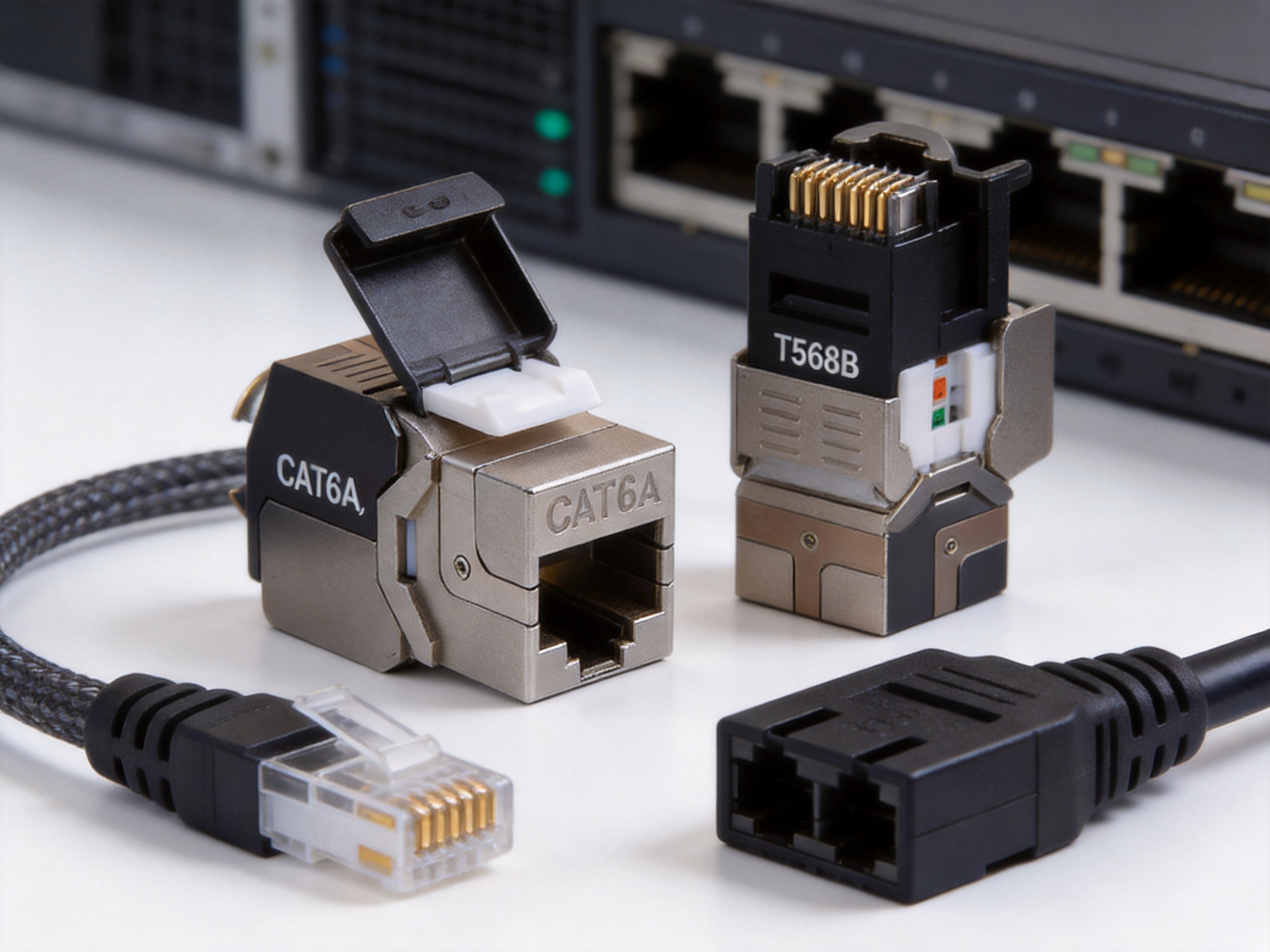
The dust-proof wire cover includes a clearly marked universal wiring sequence label. Both T568A and T568B arrangements are identified, enabling the installer to select the correct sequence for the project. This visual guide helps reduce the possibility of reversed pairs, split pairs, or incorrect conductor placement.
The label also supports quality control during installation and maintenance. A technician can quickly check the selected wiring standard without consulting a separate document for every termination. This is useful in retrofit work, service calls, and multi-team projects where installation practices must remain consistent across different rooms or buildings.
Compact 180-Degree Form
The 180-degree configuration is intended to improve cable routing flexibility. In many wall outlets and patch panels, a rear cable must turn within a limited depth. A compact jack can reduce stress on the cable jacket and help preserve the designed twist and geometry of the pairs.
Better cable routing also supports more orderly installations. Cables can be directed toward the rear or side of a panel, reducing congestion around adjacent ports. This can make labeling, testing, troubleshooting, and future moves or changes easier for network technicians.
Technical Construction and Materials
Material selection has a direct influence on connector reliability, mechanical durability, electrical performance, and resistance to environmental factors. The SMT-1047T8C6A-FTP uses a combination of metal and engineering plastic materials selected for their suitability in communication connectors.
Metal Components
The RJ45 contact pins are made from phosphor bronze with gold plating. Phosphor bronze offers useful spring properties and mechanical resilience, helping the contacts maintain pressure during repeated mating cycles. Gold plating provides a stable contact surface and helps resist oxidation at the mating interface.
The IDC card-wire terminals are made from phosphor bronze with nickel plating. The IDC section must grip the conductor insulation and establish a dependable electrical connection without requiring the conductor to be stripped in the same way as a conventional screw terminal. Nickel plating contributes to surface durability and corrosion resistance.
The external shield uses zinc alloy die-casting. Die-casting allows the manufacturer to create a precise metal housing with consistent dimensions and integrated grounding features. The resulting shell provides mechanical protection around the connector and supports the product’s electromagnetic shielding function.
Non-Metallic Components
The insulating components use PC polycarbonate and PA66 nylon 66. Polycarbonate is known for its dimensional stability and impact resistance, while PA66 is commonly used in electrical and connector applications because of its strength and resistance to mechanical wear. These materials help retain the internal contact arrangement and provide insulation between conductive elements.
The specified printed circuit board material is FR4. FR4 is a glass-fiber-reinforced epoxy laminate widely used in electrical and electronic assemblies. In a connector module, it supports the internal contact structure and provides a stable platform for the electrical design.
Gold-Plating Options
The product specification identifies a gold-plating range of 6 to 50 microinches. The appropriate plating level may depend on the customer’s application, project requirements, and purchasing specification. Gold-plated contacts are commonly selected for their ability to maintain a reliable mating surface over repeated connection cycles.
For installation in critical network environments, purchasers should confirm the exact plating thickness, cable type, shielding configuration, and testing requirements before approving the product for a project. Clear specification matching helps ensure that all components meet the intended performance level.
Electrical Performance
The jack is specified with a working voltage of 125 V and a withstand voltage of DC 1000 V, or AC 750 V, for one minute without breakdown or arcing. These values describe the electrical insulation and dielectric withstand characteristics of the connector under the stated test conditions. They are not a recommendation to use the data connector as a power-distribution component.
The initial insulation resistance is specified at not less than 100 MΩ. After a constant damp-heat test, the insulation resistance is also specified at not less than 100 MΩ. High insulation resistance helps prevent leakage between conductive elements and supports stable signal transmission.
The stated frequency range is 1 to 500 MHz. This frequency capability is aligned with the requirements commonly associated with CAT6A-oriented copper cabling. Actual channel results will depend on cable quality, termination technique, connector compatibility, patch-cord performance, grounding, bend radius, and the quality of installation.
The specification lists near-end crosstalk attenuation, NEXT, at not less than 4 dB. NEXT describes the amount of unwanted signal coupling from one pair into another near the transmitting end. A higher attenuation value generally indicates better reduction of crosstalk. Because NEXT requirements can be expressed differently depending on the test method, frequency, and applicable standard, project engineers should review complete test reports when system certification is required.
Mechanical Reliability and Durability
A network jack must remain mechanically stable throughout installation, commissioning, and years of service. The product specification limits insertion force to not more than 20 N and requires pull-out force to be not less than 20 N. These values represent the effort required to connect and disconnect the plug while helping ensure that a properly inserted plug remains secure.
The connector connection device is tested at 50 N for 60 ± 5 seconds. This type of mechanical loading test helps evaluate the ability of the assembly to resist a force applied to the connection structure. It is relevant to installations where patch cords may be moved, bundled, or subject to incidental pulling.
The product is rated for 750 plug-and-socket insertion cycles and 250 wire terminations. These figures are important for environments that frequently change patching arrangements, such as data centers, telecommunications rooms, laboratories, and network operation centers. They also provide confidence that the jack can tolerate repeated installation and maintenance work when handled correctly.
Although the jack is designed for repeated use, unnecessary force should be avoided. Patch cords should be routed with suitable strain relief, and cables should not be used to support the weight of other equipment. Good cable management extends the service life of both the jack and the connected network hardware.
Application Areas
Commercial Office Networks
Office networks often combine computers, IP telephones, wireless access points, printers, security systems, and audiovisual equipment. A modular CAT6A jack can provide a consistent connection point at each workstation. The clear wiring label assists contractors during initial construction, while the tool-free design can simplify additions and changes as tenants reconfigure their spaces.
Data Centers and Equipment Rooms
High-density equipment rooms require reliable cable organization and easy maintenance. The compact 180-degree form can help guide cables within patch panels and cabinets, while the shielded housing provides an option for installations that require additional electromagnetic protection. The jack is appropriate for use in modular distribution frames when paired with compatible hardware.
Industrial and Automation Environments
Industrial facilities may contain sources of electrical noise, including motors, drives, relays, generators, and welding equipment. In these environments, a shielded copper channel may help control electromagnetic interference. The all-metal shell and grounding design support the construction of a properly bonded shielded link.
Industrial users should assess the complete environment before selecting a connector. Temperature, humidity, chemical exposure, vibration, cable routing, and grounding practices can influence long-term performance. Where the product is used outside the stated environmental range, additional enclosure or environmental protection may be required.
Smart Homes and Building Automation
Smart homes and building automation systems increasingly use structured cabling for cameras, access control, sensors, wireless access points, audio systems, and control equipment. A modular keystone jack can be installed in wall plates, cabinets, and distribution points, providing a neat and serviceable connection method.
Education, Healthcare, and Public Facilities
Schools, hospitals, transport facilities, and public buildings often require adaptable network infrastructure. A standardized CAT6A jack allows installers to create consistent outlets across different areas. When shielded components are required, the metal housing can contribute to the overall electromagnetic compatibility strategy, provided that the complete channel is designed accordingly.
Installation Guidance
Prepare the Cable
Begin by identifying the cable type and confirming that it is a compatible 22 to 26 AWG twisted-pair cable. Plan the route before termination and maintain the manufacturer’s recommended bend radius. Avoid sharp bends, crushing, excessive pulling, and tight cable ties that could deform the cable.
Remove only the necessary amount of outer jacket. Excessive jacket removal can expose the pairs to mechanical damage and increase the distance over which the conductors are untwisted. The twists should be preserved as close as practical to the IDC termination area.
Select the Wiring Standard
Choose either T568A or T568B according to the project specification. Both standards can be used for a straight-through structured cabling channel when the same sequence is applied consistently at both ends. The most important requirement is consistency. Mixing the two sequences without a specific crossover design can result in an incorrect connection.
Arrange the Conductors
Follow the color markings on the dust-proof wire cover. Place each conductor in the assigned slot while keeping the pairs organized. Do not force a conductor into the wrong position or leave excess conductor length inside the module. Correct placement helps maintain pair balance and reduces the risk of split-pair faults.
Complete Toolless Termination
Close or secure the termination mechanism according to the product’s installation method. Confirm that each conductor is fully seated and that the IDC contacts have engaged the conductors. The outer jacket should remain supported near the termination area where the design permits.
Confirm Shield Continuity
For a shielded installation, verify that the metal shell is in contact with the shielded cable drain wire, foil, braid, or grounding element as specified by the cable and system design. The patch panel, faceplate, patch cord, and cabinet grounding arrangement should be checked as part of the same system.
Test the Completed Link
After installation, test the link using suitable cable certification equipment. Basic wire-map testing can identify open circuits, short circuits, reversed pairs, and split pairs. Certification testing can provide more detailed information about insertion loss, return loss, crosstalk, and other transmission parameters.
Testing should be performed after the cable has been routed and secured in its final position. A link that passes before installation may fail after it is bent, compressed, or moved. Accurate labeling and test-result documentation also make future maintenance more efficient.
Environmental Performance
The specified operating temperature range is -25°C to +70°C. The stated humidity condition is up to 85 percent under the specified test environment. These values indicate the environmental conditions used for product evaluation and should be considered when planning installations in warehouses, equipment rooms, industrial spaces, and other areas with changing temperature or humidity.
For outdoor locations or areas exposed to condensation, water, corrosive chemicals, oil, dust, or ultraviolet radiation, the jack should be installed inside a suitable enclosure. The connector itself should not be treated as a weatherproof product unless the complete assembly has been evaluated for the intended environment.
The product information also includes a salt-spray test method using a sodium chloride solution with a concentration of 5 ± 0.1 percent and a recommended continuous atomization duration of 48 hours. The salt solution is prepared with chemically pure or analytically pure sodium chloride and distilled or deionized water. The stated pH range before atomization is 6.5 to 7.2 at 35 ± 2°C.
Salt-spray testing is useful for evaluating resistance to corrosive atmospheres, especially where metal parts and plated surfaces are involved. It does not replace a project-specific environmental assessment. Coastal installations, marine facilities, chemical plants, and industrial sites may require additional protective measures.
Comparison with Conventional Keystone Jacks
| Feature | SMT-1047T8C6A-FTP Design | Typical Basic Unshielded Jack | Practical Benefit |
|---|---|---|---|
| Transmission category | CAT6A-oriented design, 1–500 MHz specification | May be limited to lower category or frequency | Supports demanding structured cabling applications |
| Shielding | 360-degree zinc alloy metal shell | Usually plastic housing without full shielding | Improves electromagnetic protection when the complete channel is shielded |
| Termination | Toolless IDC termination | May require a punch-down tool | Reduces tool requirements and installation time |
| Wiring guide | T568A and T568B markings on the cover | Markings may be less visible or incomplete | Helps reduce wiring errors |
| Form factor | Compact 180-degree configuration | Orientation and cable exit may be less flexible | Improves routing in restricted spaces |
| Contact material | Phosphor bronze with gold plating | Material and plating may vary | Supports stable contact and repeated mating |
| Mechanical durability | 750 plug-and-socket cycles and 250 terminations | May have lower or unspecified cycle ratings | Suitable for serviceable, changeable installations |
| Grounding design | Integrated grounding approach in the metal shell | Often not applicable to an unshielded product | Supports shield continuity in compatible systems |
This comparison should be understood as a design-level evaluation rather than a substitute for independent product testing. Different manufacturers may offer different versions of shielded CAT6A jacks, and buyers should review detailed specifications, samples, and certification documents before making a final selection.
Manufacturing Strengths and Quality Control
The manufacturer behind this product operates as an integrated network cabling and optical fiber products enterprise, combining design, research and development, sales, and service. This integrated structure is important because connector performance begins long before final assembly. Material selection, mold design, contact geometry, injection molding, plating, assembly, inspection, and packaging must work together.
The company reports nearly two decades of industry service, supported by a mature research and development system. More than ten engineers and over thirty full-time technical personnel contribute to product development, manufacturing improvement, testing, and product updates. This technical staffing structure enables the manufacturer to respond to customer specifications and improve product stability at the design source.
Manufacturing capacity includes ten regular and customization production lines, ten fully automatic injection molding machines, twenty semi-automatic injection molding machines, and eight automatic assembly machines. This equipment base supports repeatable production of plastic housings, connector components, and assembled modules. It also gives the company flexibility when customers require customized packaging, labeling, configuration, or OEM and ODM services.
Precision Injection Molding
Injection molding quality affects the dimensional accuracy of connector bodies, wire covers, alignment features, and retention structures. Automated and semi-automated molding equipment can help maintain repeatability across production batches. Consistent dimensions are especially important for keystone modules because the jack must fit into patch panels, faceplates, and distribution frames without excessive looseness or interference.
Automated Assembly
Connector assembly requires accurate positioning of contacts, insulating components, shields, covers, and grounding elements. Automatic assembly equipment can improve consistency and reduce variation caused by manual handling. Human inspection and technical oversight remain valuable for identifying surface defects, incomplete assembly, labeling issues, and other conditions that automated processes may not detect independently.
Performance Testing
The company emphasizes performance testing as part of its quality approach. Electrical, mechanical, environmental, and durability characteristics can be evaluated against product requirements and customer specifications. Testing may include insulation resistance, dielectric withstand, insertion and withdrawal force, connector retention, mating durability, cable termination performance, and environmental exposure.
For structured cabling customers, product-level testing should be complemented by channel-level testing after installation. The manufacturer’s controlled factory inspection and the installer’s field certification serve different purposes. Together, they provide a stronger quality assurance process.
OEM and ODM Support
Network infrastructure projects often require more than a standard catalog item. Customers may request a particular color, label, packaging format, plating specification, shielding configuration, or installation method. The manufacturer’s production lines and engineering resources support customized OEM and ODM projects, allowing distributors, system integrators, and network brands to develop products suited to their market requirements.
Customization should be managed through controlled documentation. A clear product drawing, bill of materials, approved sample, inspection standard, and packaging specification can help ensure that repeat orders remain consistent. This is especially important for large international projects where the same product may be supplied over an extended period.
Packaging, Storage, and Logistics
Each product is placed in a dedicated blister bag and then packed in a cardboard box. Accessories are placed with the product, and a label identifying the model and quantity is affixed to the upper-left area of the carton front. This packaging arrangement helps protect the jack during handling and allows warehouse staff to identify the contents efficiently.
The regular packing quantity is 50 pieces per box, with 10 boxes per carton, for a total of 500 pieces per carton. Customer-specified packaging is available according to the product note. Distributors can therefore request packaging and labeling arrangements that align with their inventory, retail, or project-delivery systems.
Packaged products should be stored in a warehouse with an ambient temperature of -5°C to +30°C and relative humidity not exceeding 70 percent. The surrounding air should be free from acid, alkali, and other corrosive gases. Under the stated storage conditions, the storage period is three years.
Proper storage protects plated contacts, plastic materials, labels, and packaging from unnecessary deterioration. Cartons should remain dry and should not be stored directly on damp floors. Heavy objects should not be placed on top of the product cartons, and stock should be rotated according to the receiving date.
Why This Product Is Suitable for Professional Projects
Professional structured cabling projects require more than a low purchase price. Installers and system integrators must consider labor time, compatibility, test performance, field service, documentation, durability, and future expansion. The 180-degree shielded CAT6A toolless keystone jack addresses these factors through a balanced set of design features.
Its shielded zinc alloy shell provides an option for environments where electromagnetic interference is a concern. The tool-free termination method can reduce installation complexity. The compact form helps with cable routing, while the visible wiring guide supports consistent field work. Gold-plated phosphor bronze contacts, a specified durability of 750 mating cycles, and an IDC range of 22 to 26 AWG contribute to practical long-term use.
The product is also supported by a manufacturer with dedicated engineering personnel, multiple production lines, injection molding resources, automatic assembly equipment, performance testing capabilities, and international supply experience. These factors can be valuable for distributors and contractors that need stable production, customization support, and repeatable product quality.
Compared with a basic unshielded jack, this product is particularly attractive when a project requires a higher category, an all-metal shield, a compact rear orientation, and a convenient termination process. Compared with a more complicated shielded jack, its toolless construction may help installers complete work more quickly and with fewer tools.
Selection Considerations for Buyers
Before ordering, buyers should confirm the required category, shield type, connector orientation, cable gauge, contact plating, patch-panel compatibility, and applicable standards. The jack should be evaluated as part of a complete channel rather than as an isolated component.
Buyers should also clarify whether the project requires T568A, T568B, or a specific labeling format. For large installations, it is useful to request samples for fit testing in the intended faceplate or patch panel. This can reveal clearance issues before mass deployment.
Environmental requirements should be reviewed carefully. The stated temperature and humidity conditions may be suitable for many indoor applications, but harsh industrial or outdoor environments may require an enclosure, additional sealing, or a different connector design.
For shielded systems, grounding and bonding requirements should be included in the project specification. The shielded jack, cable, patch panel, patch cord, rack, and building grounding system must work together. A disconnected or improperly bonded shield can reduce the effectiveness of the overall design.
Maintenance and Troubleshooting
Routine maintenance begins with visual inspection. Technicians should check that the module is fully seated, the patch cord is correctly inserted, and the cable is not under excessive tension. The metal shield should be free from visible damage, and the grounding path should remain secure.
If a link fails a wire-map test, inspect the termination sequence first. Open conductors, reversed pairs, split pairs, and incomplete IDC contact are common causes of failure. If the wire map passes but performance remains below expectation, inspect bend radius, cable compression, pair untwist, patch-cord category, and possible electromagnetic interference sources.
Intermittent faults may result from a loose plug, damaged contact, cable movement, or poor shield continuity. Replacing the patch cord can help isolate the problem. If the fault remains, test the jack and cable independently using approved certification equipment.
Keystone jacks are designed to be replaceable components. If a module has been damaged or repeatedly reterminated, replacement is often more efficient than attempting extensive repair. The modular design supports easier maintenance and helps minimize downtime.
Frequently Asked Questions
What type of product is the SMT-1047T8C6A-FTP?
It is a 180-degree shielded CAT6A toolless keystone jack for structured copper cabling systems. It provides an RJ45 interface at the front and an IDC termination interface at the rear.
Does the jack support both T568A and T568B?
Yes. The wiring sequence markings identify both T568A and T568B arrangements. Installers should select one sequence and apply it consistently throughout the intended link.
What cable size is supported?
The IDC terminal is specified for 22 to 26 AWG twisted-pair cable. Cable construction and diameter should also be checked for compatibility before installation.
Why is the metal shell important?
The zinc alloy shell provides mechanical protection and 360-degree shielding around the connector. When used with compatible shielded cable and properly grounded system components, it can help reduce electromagnetic interference.
Can the jack be installed in a patch panel?
Yes. Its embedded modular design is intended for installation in compatible modular patch panels and distribution frames. Fit should be confirmed with the selected panel before large-scale deployment.
Does toolless mean no installation preparation is required?
No. Toolless termination reduces the need for a punch-down tool, but the cable must still be prepared correctly. The installer must select the wiring standard, preserve pair twists, position each conductor accurately, secure the termination, and test the finished link.
How durable is the connector?
The stated durability is 750 plug-and-socket insertion cycles and 250 wire terminations. These values indicate suitability for installations that may undergo repeated maintenance, patching, or reconfiguration.
What materials are used for the contacts?
The RJ45 contact pins use gold-plated phosphor bronze. The IDC card-wire terminals use nickel-plated phosphor bronze. The housing includes PC polycarbonate and PA66 nylon 66 components, while the shield is made from zinc alloy die-casting.
What is the operating temperature range?
The specified environmental temperature range is -25°C to +70°C. Installations outside this range should be reviewed with the supplier and protected using suitable environmental controls.
How should the product be stored?
It should be stored at -5°C to +30°C, with relative humidity no higher than 70 percent, in an area free from acid, alkali, and other corrosive gases. The stated storage period is three years under these conditions.
Can customized packaging be requested?
Yes. The product note identifies customer-specified packaging as an option. Packaging, labeling, and other project requirements should be confirmed before production.
Is the product suitable for OEM or ODM projects?
The manufacturer supports OEM and ODM projects and operates regular and customized production lines. Customers should provide drawings, technical specifications, labeling requirements, and inspection standards for review.
Does a shielded jack eliminate all electromagnetic interference?
No. Shielding is one element of electromagnetic compatibility. The cable, patch cords, panels, grounding system, routing, and nearby electrical equipment must also be considered. An improperly grounded or partially shielded channel may not achieve the expected result.
Conclusion
The 180-degree shielded CAT6A toolless keystone jack is designed for structured cabling applications that require high-frequency performance, practical installation, and improved electromagnetic protection. Its 1 to 500 MHz frequency specification, high-low contact arrangement, 360-degree zinc alloy shielding, compact rear orientation, and clearly marked T568A and T568B wiring guide make it a strong option for professional network infrastructure.
The use of gold-plated phosphor bronze contacts, nickel-plated IDC terminals, PC and PA66 insulating materials, and FR4 construction supports mechanical and electrical reliability. The stated insertion-cycle, wire-termination, insulation, dielectric, and environmental specifications provide useful criteria for project evaluation.
Equally important, the product is backed by an established manufacturer with engineering personnel, injection molding resources, automatic assembly equipment, multiple production lines, customization capabilities, and experience serving international markets. This combination of product design and manufacturing strength can help distributors, contractors, and system integrators build consistent copper structured cabling solutions.
For best results, the jack should be installed as part of a complete CAT6A shielded channel, with compatible cables and accessories, correct grounding, careful cable preparation, and field certification testing. When these conditions are met, the product can provide a neat, serviceable, and dependable connection point for modern data, communication, automation, and smart-building networks.
References
1. YD/T 926.1-2009, General Specifications for Communication Cabling Components.
2. YD/T 926.3-2009, Applicable Sub-Standard for Communication Cabling Components.
3. TIA-568 Series, Balanced Twisted-Pair Telecommunications Cabling and Component Requirements.
4. ISO/IEC 11801 Series, Information Technology — Generic Cabling for Customer Premises.
5. IEC 60512 Series, Connectors for Electronic Equipment — Tests and Measurements.
6. RoHS Environmental Compliance Requirements for Electrical and Electronic Products.
7. Manufacturer product specification for the SMT-1047T8C6A-FTP 180-Degree Shielded CAT6A Toolless Keystone Jack.